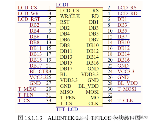
TFT(Thin Film Transistor)即薄膜场效应晶体管,
它可以“主动地”对屏幕上的各个独立的像素进行掌握,这样可以大大提高反应韶光。一样平常TFT的反应韶光比较快,约80毫秒,而且可视角度大,一样平常可达到130度旁边,紧张利用在高端产品。从而可以做到高速率、高亮度、高比拟度显示屏幕信息。TFT属于有源矩阵液晶显示器,在技能上采取了“主动式矩阵”的办法来驱动,方法是利用薄膜技能所作成的电晶体电极,利用扫描的方法“主动拉”掌握任意一个显示点的开与关,光源照射时先通过下偏光板向上透出,借助液晶分子传导光芒,通过遮光和透光来达到显示的目的。

在基于Arduino的项目中,处理器频率很低。因此无法显示繁芜的高清图像和高速运动。因此,全彩色TFT LCD只能用于显示大略的数据和命令。

现在大部分TFT屏幕模块都附带一个sd卡读写器和触摸屏。
.
市情上TFT LCD有很多种,利用不同的掌握芯片,以是你利用的库文件必须支持屏幕的主控芯片。本次教程仅以arudino自带的TFT库为例,显示芯片7735
屏幕可以通过两种办法配置。一个是利用Arduino的硬件SPI接口。另一种方法是手动声明所有引脚。这两种方法在屏幕功能上没有差异,但是利用硬件SPI要快得多。
如果须要在TFT模块上利用SD卡,则必须利用硬件SPI。库中的所有示例都是为SPI利用的硬件编写的。
如果在Uno中利用硬件SPI,您只须要声明CS、DC和复位引脚,由于MOSI (pin 11)和SCLK (pin 13)已经定义。
安装库
Adafruit GFX:https://github.com/adafruit/Adafruit-GFX-Library
Adafruit ST7735 libraries:https://github.com/adafruit/Adafruit-ST7735-Library
默认情形,屏幕是横放的,左上角的点的坐标是0,0。如果这个点移动到屏幕的右上角,它的坐标是0,159;左下角的坐标是127,0,右下角的坐标是127,159。
可以通过调用setRotation(0)以垂直方向(也称为“竖屏”)利用屏幕。当您调用这个函数时,x轴和y轴相应地发生变革,对screen.width()或screen.height()的调用也会发生变革。
屏幕可以显示16位的颜色。赤色和蓝色各有5位分辨率(32级赤色和蓝色),绿色有6位分辨率(64级)。为了与其他运用程序保持同等,库以8位的值处理红、绿和蓝通道的颜色(0-255),并适当缩放颜色。
上代码#include <TFT.h> // Hardware-specific library
#include <SPI.h>
#define CS 10
#define DC 9
#define RESET 8
TFT myScreen = TFT(CS, DC, RESET);
//在setup()中,须要用begin()启动库,然后用background()添补玄色以打消屏幕。
void setup(){
myScreen.begin();
myScreen.background(0,0,0); // clear the screen with black
delay(1000); // pause for dramatic effect
}
//在loop()中,要在屏幕上画一条线,调用line()。line()接管四个参数,开始的x和y坐标,结束的x和y坐标。要绘制一个框,利用rect()。rect()也接管四个参数:左上角的x和y坐标,然后是像素的宽度和像素的高度。在每个调用之间,利用stroke()或fill()变动颜色。stroke()将变动线条或形状周围的轮廓的颜色。fill()变动形状的内部颜色。
void loop(){
myScreen.stroke(255, 0, 0); // set the stroke color to red
myScreen.line(0, 10, myScreen.width(), 10); // draw a line across the screen
delay(1000);
myScreen.noStroke(); // don't draw a line around the next rectangle
myScreen.fill(0,255,0); // set the fill color to green
myScreen.rect(0,20,myScreen.width(),10); //draw a rectangle across the screen
delay(1000);
myScreen.fill(0,0,255); // set the fill color to blue
myScreen.stroke(255,255,255); // outline the rectangle with a white line
myScreen.rect(0,45,myScreen.width(),45); // draw a fat rectangle
delay(1000);
myScreen.background(0,0,0); // clear the screen before starting again
delay(1000);
}
//TFT库包含用于在屏幕上绘制文本的基本字体。默认情形下,字符宽5像素,高8像素。可以将字体大小变动为10x16、15x24或20x32。
在本例中,创建一个基本计数器,它将每半秒在屏幕上更新一个数字。与前面的示例一样,在setup()之前包含必要的库和变量。
#include <TFT.h> // Hardware-specific library
#include <SPI.h>
#define CS 10
#define DC 9
#define RESET 8
// pin definition for the Leonardo
// #define CS 7
// #define DC 0
// #define RESET 1
TFT myScreen = TFT(CS, DC, RESET);
// variable to keep track of the elapsed time
int counter = 0;
// char array to print time
char printout[4];
void setup(){
myScreen.begin();
myScreen.background(0,0,0); // clear the screen
myScreen.stroke(255,0,255);
// static text
myScreen.text(\公众Running for\"大众,0,0);
myScreen.text(\"大众seconds\"大众,0,30);
// increase font size for text in loop()
myScreen.setTextSize(3);
}
在loop()中,将获得当前韶光,并将该数字存储在char数组中。在每个循环结束之前,删除前面编写的文本,这样它就不会覆盖自己。
TFTvoid loop(){
// get elapsed time
counter = millis();
// convert to a string
String elapsedTime = String(counter/1000);
// add to an array
elapsedTime.toCharArray(printout,4);
// print out and erase
myScreen.stroke(255,255,255);
myScreen.text(printout,0,10);
delay(1000);
myScreen.stroke(0,0,0);
myScreen.text(printout,0,10);}
从SD卡中绘制图像
TFT库能够从SD卡上读取.bmp文件并将其显示在屏幕上。图像可以小于或大于屏幕分辨率(160x128),但是Arduino上没有用于图像操作的方法。在将图片放到SD卡上之前,该当先调度图片的大小。
不才面的示例中,名为“arduino”的位图为160x128像素。bmp”位于SD卡的根目录中。当由库读取并绘制时,图像将填满屏幕。
// include the necessary libraries
#include <SPI.h>
#include <SD.h>
#include <TFT.h> // Hardware-specific library
// pin definition for the Uno
#define SD_CS 11
#define LCD_CS 10
#define DC 9
#define RESET 8
// pin definition for the Leonardo
// #define SD_CS 8
// #define LCD_CS 7
// #define DC 0
// #define RESET 1
TFT myScreen = TFT(LCD_CS, DC, RESET);
// this variable represents the image to be drawn on screen
PImage image;
void setup() {
// initialize the serial port
Serial.begin(9600);
while (!Serial) {
// wait for serial line to be ready
// needed for the Leonardo
}
// try to access the SD card
Serial.print(\"大众Initializing SD card...\"大众);
if (!SD.begin(SD_CS)) {
Serial.println(\"大众failed!\公众);
return;
}
Serial.println(\"大众OK!\"大众);
// initialize and clear the GLCD screen
myScreen.begin();
myScreen.background(255, 255, 255);
// load the image from the SD card
image = myScreen.loadImage(\公众arduino.bmp\"大众);
// check if the image loaded properly
if (image.isValid() != true) {
Serial.println(\"大众error while loading arduino.bmp\公众);
}
//write the image on screen
myScreen.image(image, 0, 0);
}
void loop(){
// nothing happening here
}
函数命令详解:https://www.arduino.cn/forum.php?mod=attachment&aid=MjIwMTZ8NWZkYTFhMzh8MTU2MTk1ODk5MXwxNTM4NjF8MjI4NDU=
下一期,我们先容TFT屏的触控运用


